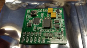
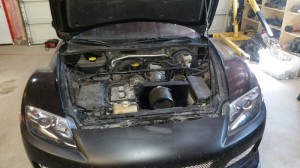
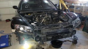
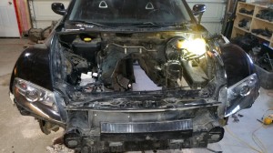
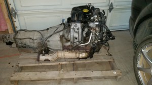
Looks like the first version of the VPW to CAN Bus boards just arrived. Time to start testing them.
Month: June 2015
More Turbo Pipe
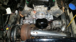
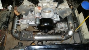
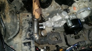
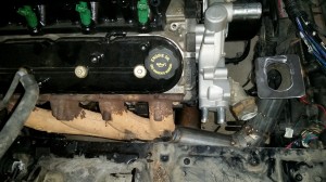
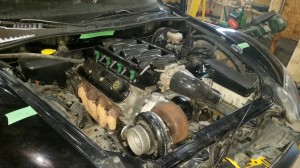
I finished most of the hot side turbo pipe tonight. I had to make some changes to it from the last post and I also modified the motor mounts.
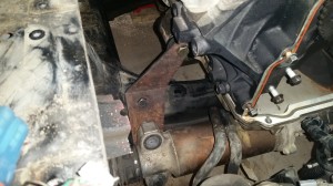
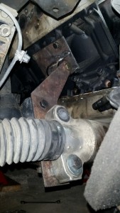
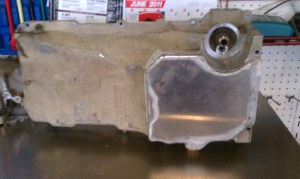
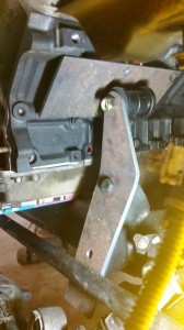
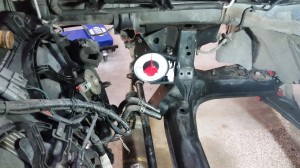
For the mounts, I re-drilled the 1/2″ bushing holes 7/8″ lower. This will allow the hood to close with the Speedmasters intake that I have. But I will have to buy a F-Body oil pump instead of cutting and welding the truck pan. The main reason is that the F-Body pan is 1″ shorter in the front and allows better steering rack clearance. I will post a final mount drawing when I pull the motor for assembly and re-cut the plates for the hole changes.
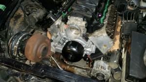
On the turbo side I moved the exhaust plate lower and towards the center more. This placement seems to give good clearance for the belts and water pump outlets. I also started on the 3″ down pipe and I think I have a good placement for the wastegate. Once everything is tacked in place I will cut where needed to allow for V-band clamps and do the final welding.
Turbo Hot Side Begins
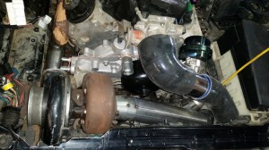
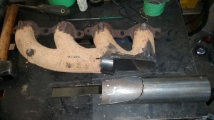
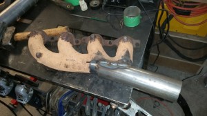
I started plumbing the hot side of the turbo system tonight. Cut the truck manifolds so they would exit straight forward and tacked on 2.5″ tubing. I didn’t feel like waiting for mandrel bend sections, so everything will be pie cut pieces.
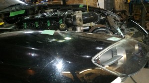
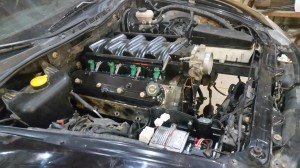
I also tested the hood closure and found out that I need to modify the main rack/motor plates to drop the rack and motor about 3/4″ so the hood will clear the throttle body. This will also drop the turbo lower, so I plumbed it a little higher.
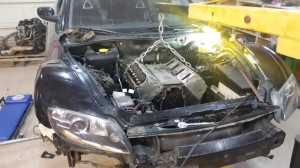
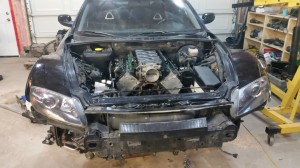
Engine Sitting on its Own Mounts
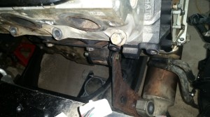
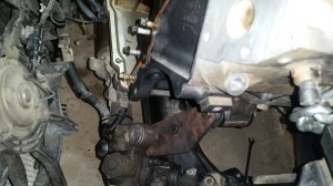
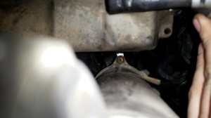
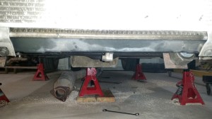
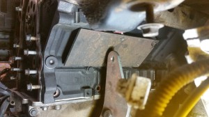
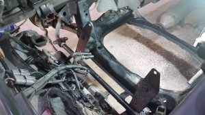
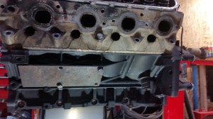
I welded up the bushings to the motor plates tonight. One bolted the steering rack and set the bolts through the bushings into the main mounts. Everything is looking good clearance wise, so now I can add the rest of the main mount plates to strengthen them. I also took a picture showing how low the 5.3 truck oil pan hangs down. This will need to be cut and a new bottom plate will be welded in (see example picture).
Next up will be the transmission mount.
More work on the motor mounts
Motor Mounts Started
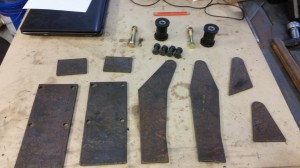
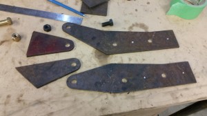
I got the prototype mounts cut out today on a plasma table out of 3/16″ plate.
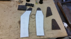
I then printed a drill template to punch and drill the mount holes (1/2″). My initial drawing is off by a few mm on the hole spacing for the steering rack. I also only marked the rack location just in case it needs to change once the motor is mocked in place.
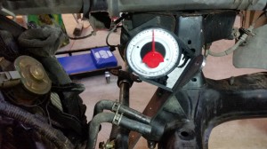
I also figured out that the bend in the mount plate is around 25 degrees.
